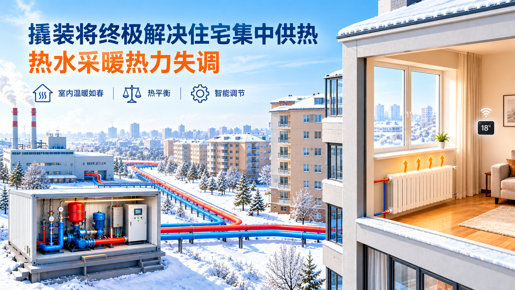
China began centralized heating in the 1970s. Thermal imbalance in residential heating has plagued the industry for decades. Why so hard? Earth climate swings while human comfort needs stay fixed. Stove heating had no imbalance; centralized heating created it. We cannot regress to stoves—understanding the cause is the only way to solve it.
China began centralized heating around the 1970s — more than seventy years ago. The problem of thermal imbalance in residential apartment-block heating has continued to trouble the industry to this day, becoming a long-standing hard nut to crack. Why is it so difficult? Is it truly unsolvable?
The earth's environment that we live in is influenced by the sun. Day and night alternate; spring gives way to summer, autumn and winter; wind, frost, rain and snow change unpredictably. In contrast, the comfortable thermal environment that humans need is relatively fixed. Specifically for northern residences, heating is essential in winter. Otherwise people feel extreme discomfort, even unable to survive. The mission of centralized-heating practitioners is to provide a small, stable environment. Whether it is bright sunshine or a raging snowstorm outside, the interior of residences should remain warm like spring. The process of achieving this goal is reaching an ideal thermal equilibrium. In the era of stove heating, achieving thermal equilibrium was a simple matter. In earlier years there was no such thing as thermal imbalance. It was only after centralized heating was implemented that thermal imbalance appeared. Solving thermal imbalance certainly cannot mean regressing to stove heating. Only by understanding why centralized heating produces thermal imbalance can we fundamentally solve the problem that has plagued the industry for decades.
Heating Thermal Equilibrium
To keep the interior of residential apartments at a set comfortable environment, e.g. 18°C. When the daily average outdoor temperature is lower than 18°C, heat must be released indoors to maintain the ideal indoor–outdoor thermal equilibrium. The equilibrium relation is:
Formula 1: Q₁ = F₁ · K₁ · (tin − ta)
Symbols:
Q₁— heat delivered into the room, W
F₁— building envelope area, m²
K₁— comprehensive heat-transfer coefficient of the building envelope, W/(m²·°C)
tin— indoor temperature, °C
ta— average outdoor temperature, °C
Heat Released by Radiators
Heat is delivered into the room through radiators:
Formula 2: Q₂ = F₂ · K₂ · ((ts + tr)/2 − tin)^1.3
Symbols:
Q₂— heat released by radiators into the room, W
F₂— radiator heat-dissipation area, m²
K₂— radiator heat-release coefficient, W/(m²·°C)
ts— supply water temperature, °C
tr— return water temperature, °C
Heat Delivered to the Heating Room
Hot water conveys heat to the radiators through the supply pipe:
Formula 3: Q₃ = G · Cp · (ts − tr) × 3.6⁻¹
Symbols:
Q₃— heat delivered by the heating system into the room, W
G— circulating water flow supplied to the heating room, kg/h
Cp— constant-pressure specific heat of water, kJ/(kg·°C)
To maintain a constant indoor temperature tin (e.g. 18°C) under any outdoor temperature ta, the supply and the loss must be balanced, i.e.:
Formula 4: Q₁ = Q₂ = Q₃
Since this discussion concerns hot-water heating, before analyzing the equilibrium relations above we must also list the hydraulic formula for hot water flowing in pipes and related equipment (radiators, elbows, valves…):
Formula 5: ΔP = H · G²
Symbols:
ΔP— the driving force that moves water in the pipe, here called head, MPa
H— hydraulic resistance coefficient of the water system, MPa/(t/h)²
G— water flow, t/h
Heating Operation Adjustment
In Formula 1, the variable is the outdoor air temperature ta; the other parameters are not variables. In Formula 2, the variables are supply temperature ts and return temperature tr. ts is the active variable, tr is the passive variable. In Formula 3 another variable appears: G, the circulating water flow. According to the outdoor temperature ta, the heating operation engineer specifies a supply water temperature value ts and a circulating water flow value G. After the system reaches a stable state, a stable indoor temperature tin and return temperature tr are obtained. Checking the room temperature tin, if it is lower than the set value, the circulating water flow G can be increased. As G increases, the return temperature tr rises. The average surface temperature of the radiator increases, the radiator releases more heat, and eventually the room temperature tin rises. This method is called flow adjustment (quantity regulation); if the circulating water volume G is not changed, the supply water temperature ts can be raised. When ts rises, the return temperature tr also rises. The heat brought into the room increases, achieving the purpose of raising room temperature tin. This adjustment method is called temperature adjustment (quality regulation). Of course one can also simultaneously change both flow G and supply temperature ts to raise room temperature tin. This method is called quality–quantity adjustment.
Theoretically, the problem is quite simple. There is only one variable — the outdoor temperature ta. Outdoor temperature does not change drastically in a very short time, let alone alternate. From Formula 1 it is easy to obtain the required heat Q₁; then from Formulas 2 and 3 the flow G and the supply/return water temperatures ts, tr are readily obtained. Then why has user thermal imbalance become an industry-wide problem lasting decades? Naturally there is a reason. Looking back at Formula 1, the building envelope area F₁ is a fixed value. The last remaining parameter K₁ is not a variable. But for users in the same area, the value of K₁ is not unique. The K₁ value of each building may differ markedly from that of other buildings; the K₁ value of the same building also varies at different times. In contrast, flow G and supply temperature ts are variables, adjustable and controllable. K₁ cannot be adjusted. The main factors related to K₁ are as follows:
1. Sunlight exposure
Walls receiving sunlight gain heat from it. Rooms on the top floor get ample sunlight; lower-floor rooms may be blocked by buildings in front and receive no sunlight. The difference in sunlight entering through window glass has the same effect. The orientation of rooms also determines the difference in heat gain through sunlight.
2. Cold-air infiltration
Strong wind hitting a building facade creates wind pressure. Under wind pressure, cold air enters the room through gaps in doors and windows. The incoming cold air pushes out the warm air inside, lowering the indoor temperature. Different wind intensities affect room heat loss differently. Rooms of different orientations are affected by wind to different degrees. Rooms at different floor heights are also affected differently by wind. Wind direction is changeable, so outdoor wind makes the building's heat load fluctuate unpredictably.
3. Stack effect
The indoor temperature of a heated building may be 18°C, while the outdoor temperature may be −18°C. Hot air is light, cold air is heavy. The density difference between indoor and outdoor air causes hot air to escape from gaps in doors and windows of upper-floor rooms, while cold air infiltrates the building from various holes, openings and cracks at the bottom. The height of the building is positively correlated with the stack effect; the colder the time and region, the stronger the stack effect. The taller the building, the stronger the stack effect. The stack effect harms lower-floor residents more than upper-floor ones, with bottom-floor residents suffering the most.
4. Influence of radiator area F₂
Another factor affecting heating operation adjustment is F₂ in Formula 2. F₂ is the radiator area. F₂ is a fixed, unchanging parameter. F₂ does not change during heating, but F₂ can be changed. With all other factors unchanged, replacing the radiator with a larger one will significantly raise that room's indoor temperature tin. Adjacent rooms whose radiator area F₂ was not changed see no temperature change. In the era of welfare housing allocation this rarely happened and had little impact on centralized-heating operation management. But after residences became commercial commodities, the radiator area F₂ became uncontrollable. Its impact on traditional centralized-heating operation is inevitable and difficult to control.
5. Water-system driving and hydraulic relations
Water in the system flows in pipes when driven. The stronger the driving action, the greater the water flow velocity. Under a given driving intensity, increasing the system's resistance lowers the water flow velocity. Formula 5 describes the hydraulic relation mentioned above.
In hot-water heating systems, a circulating pump is usually installed to make water flow. Here, the "driving action" provided by the pump driven by a motor is called mechanical head, denoted ΔPp. Relative to pump driving, hot-water heating systems can also adopt natural circulation. A hot-water heating system always has one supply pipe and one return pipe. Water in the supply pipe has a higher temperature; water in the return pipe has a lower temperature. Higher-temperature water has lower density; lower-temperature water has higher density. When the supply and return pipes are arranged vertically, water circulates under the density difference. The greater the vertical height of the supply and return pipes, the stronger the flow of water of different densities. Circulation in a system without a pump is called natural circulation. The driving action that constitutes natural circulation is called the natural (gravity) head, denoted ΔPρ. A hot-water heating system may have no pump. Of course, without a pump there is no mechanical head ΔPp. But the system always has a gravity head ΔPρ. When the pump's driving action is absolutely dominant, all water in the system flows from the supply pipe through the radiator and then into the return pipe; if the pump's action is weak — so weak as to be negligible — one finds that the circulating water of upper floors flows from the supply pipe through the radiator into the return pipe. From top to bottom, the water flow intensity of each floor attenuates step by step. The bottom-floor water flows from the return pipe through the radiator into the supply pipe. This phenomenon or action is unavoidable. And it causes great interference to heating operation adjustment. The commonly seen "upper floors hot, lower floors cold" is an important cause of this.
Near-hot, far-cold
Near-hot, far-cold is another common phenomenon in centralized heating pipe networks. "Near" and "far" refer to the distance from the heat user to the heating station. The hot water sent from the heating station to each heat user in a centralized heating system has the same temperature (ignoring the effect of heat dissipation along the way on water temperature). According to Formula 3, the larger the flow G, the more heat Q the user receives. Ignoring the effect of gravity head ΔPρ, all users on the heat network obtain the driving force for hot water from the same circulating pump at the heating station. In Formula 3, ΔP replaces the mechanical head of the pump. If all heat users need the same amount of circulating water flow G, then the resistance of the pipeline between each heat user and the heating station should be equal. The longer the pipeline, the greater the resistance. The smaller the pipe diameter, the greater the resistance. Various fittings on the pipeline such as valves, elbows and reducers constitute local resistance.
Formula 6: H = 0.00103(L + L') × 10⁻⁶ × (ρ · din^5.25)⁻¹
Symbols:
H— resistance coefficient of the circulating water pipeline, MPa/(t/h)²
L— pipeline length, m
L'— equivalent length converted from local resistance formed by fittings in the pipeline, m
ρ— water density, kg/m³
din— pipeline inner diameter, m
If a centralized heating pipe network has no intermediate pipe pumps, then all users on the network share the driving head ΔP provided by the same pump(s). Without intervention, the closer a user is to the pump station, the shorter the pipeline length L between it and the station, and the more circulating water it receives, resulting in the near-hot, far-cold thermal imbalance.
For this, numerous regulating valves are installed throughout the network. Closing the valve opening increases local resistance, hoping to achieve hydraulic balance across the whole network. However, this work is extremely difficult. The disorderly, randomly changing and numerous related parameters (such as outdoor wind force and direction) make adjustment exceedingly difficult. The problem is that we set ourselves an impossible and also unnecessary target (for example, all heat users maintaining room temperature 18±1°C throughout). As a result, thousands of practitioners spent fifty to sixty years unable to achieve it. Change the thinking: do not try to take on everything. Use the user entry device (skid-mounted unit) to isolate household from network. Macro adjustment is handled by the heat-network operation engineer. Room-temperature micro-adjustment is left to the heat users themselves. Incorporate the principle of "pay more for what you take" (though it need not be the only condition), and user dissatisfaction with the heat network will decline. The workload of heat-network operators will be significantly reduced. Heating energy consumption (heat, electricity, water) will be markedly lowered. It is expected that introducing skid-mounted units will bring revolutionary change to the centralized hot-water heating industry.
The hydraulic adjustment of the pipe network no longer directly affects the hydraulic conditions of heat users. Hydraulic condition adjustment among users in one building will not affect users in other buildings at all. Thermal imbalance in centralized hot-water heating will become history.